Week 1
Setting Up A Breadboard
The things I have:
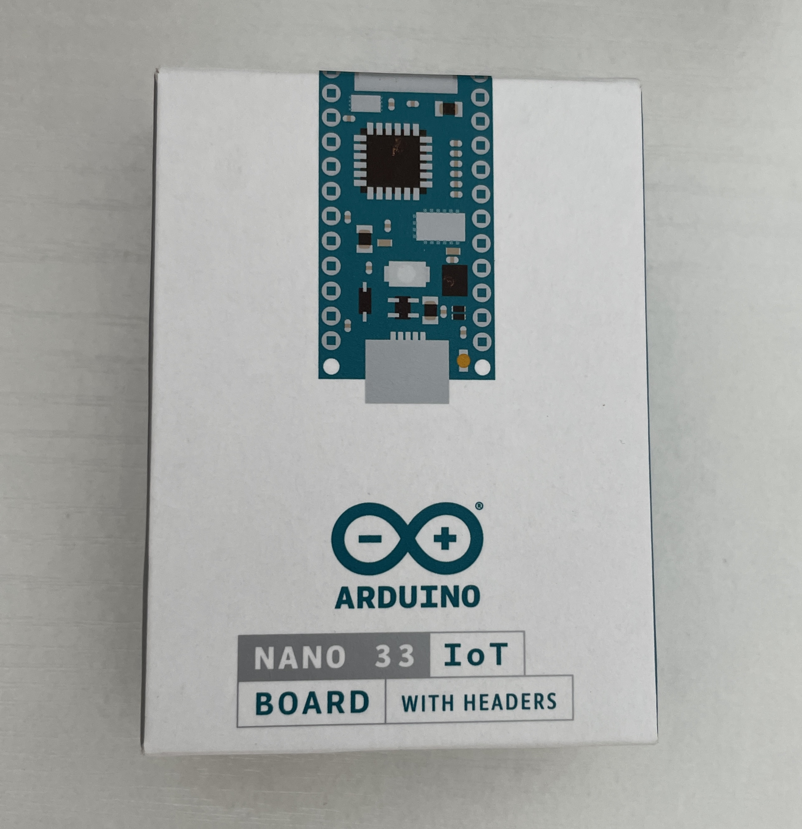
NANO 33 IoT
 USB cable
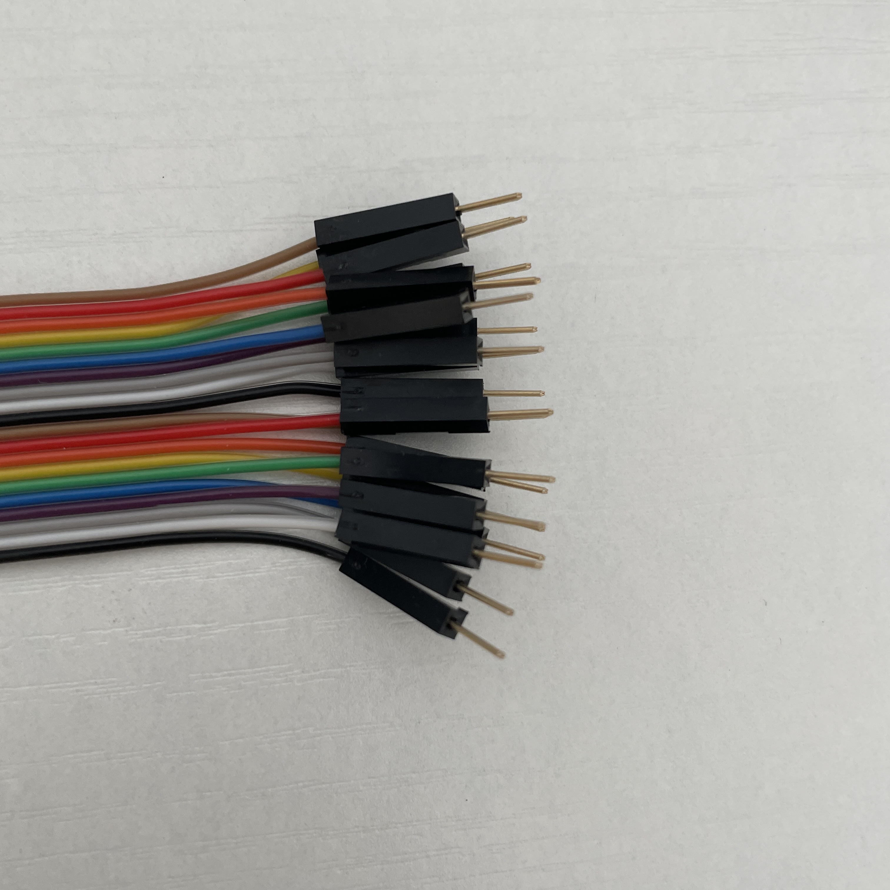
wire
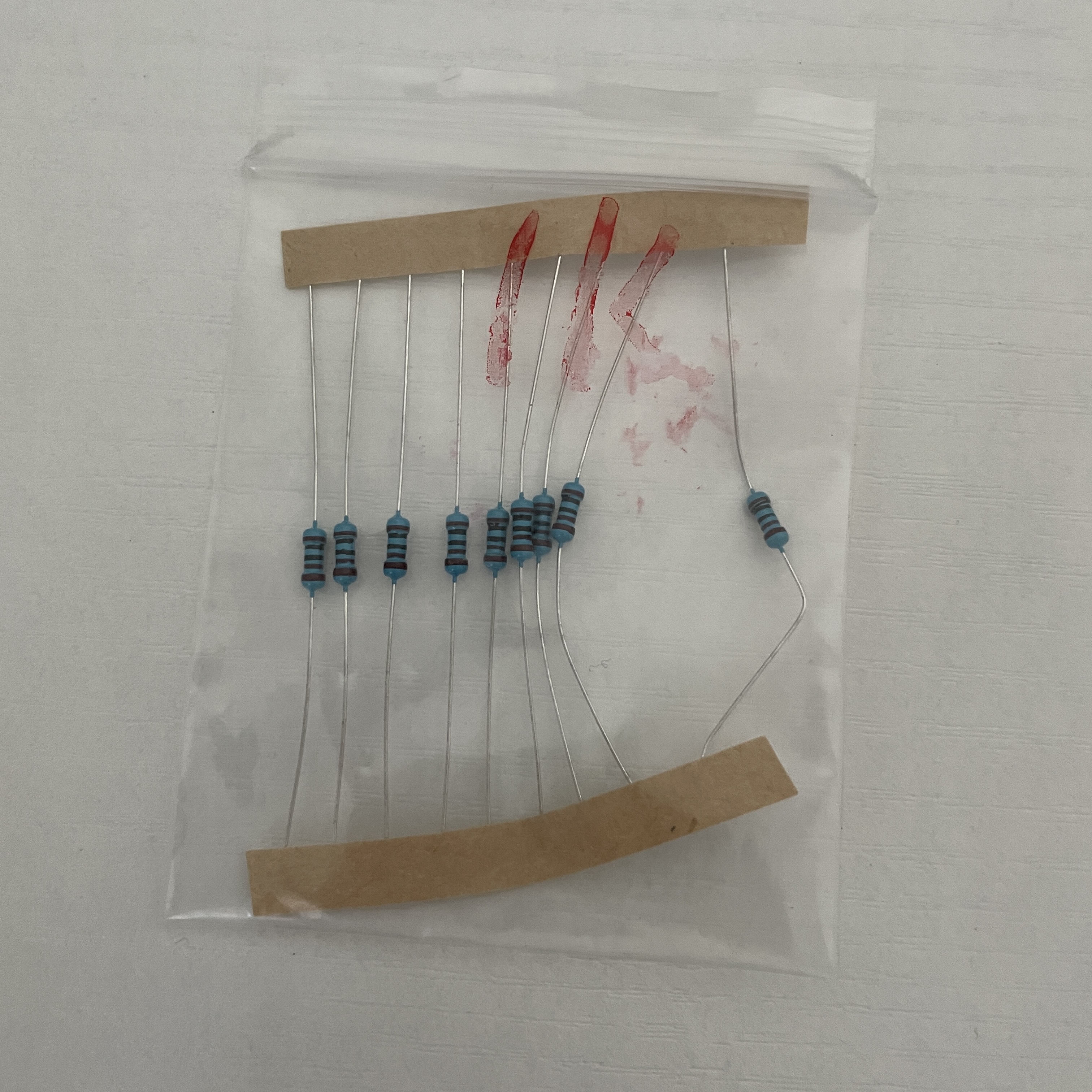 1KΩ resistance
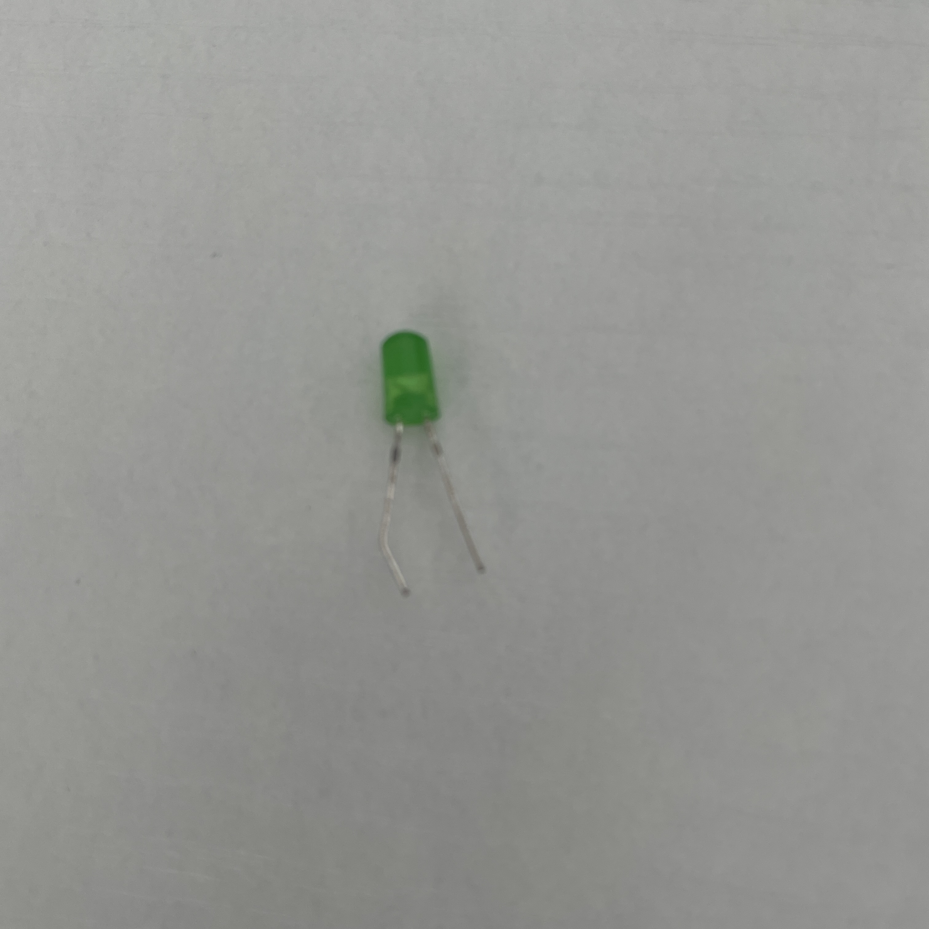
LED
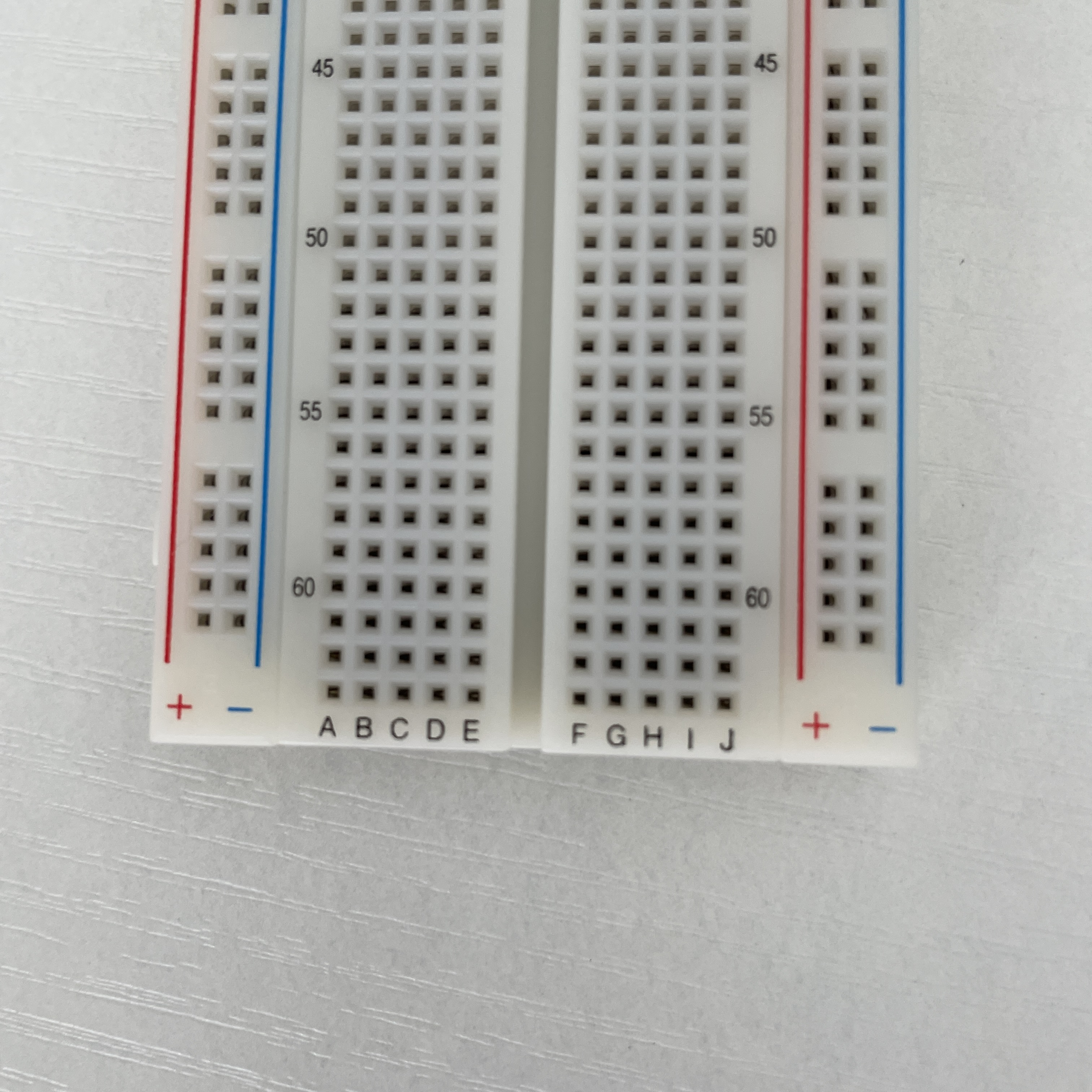
breadboard
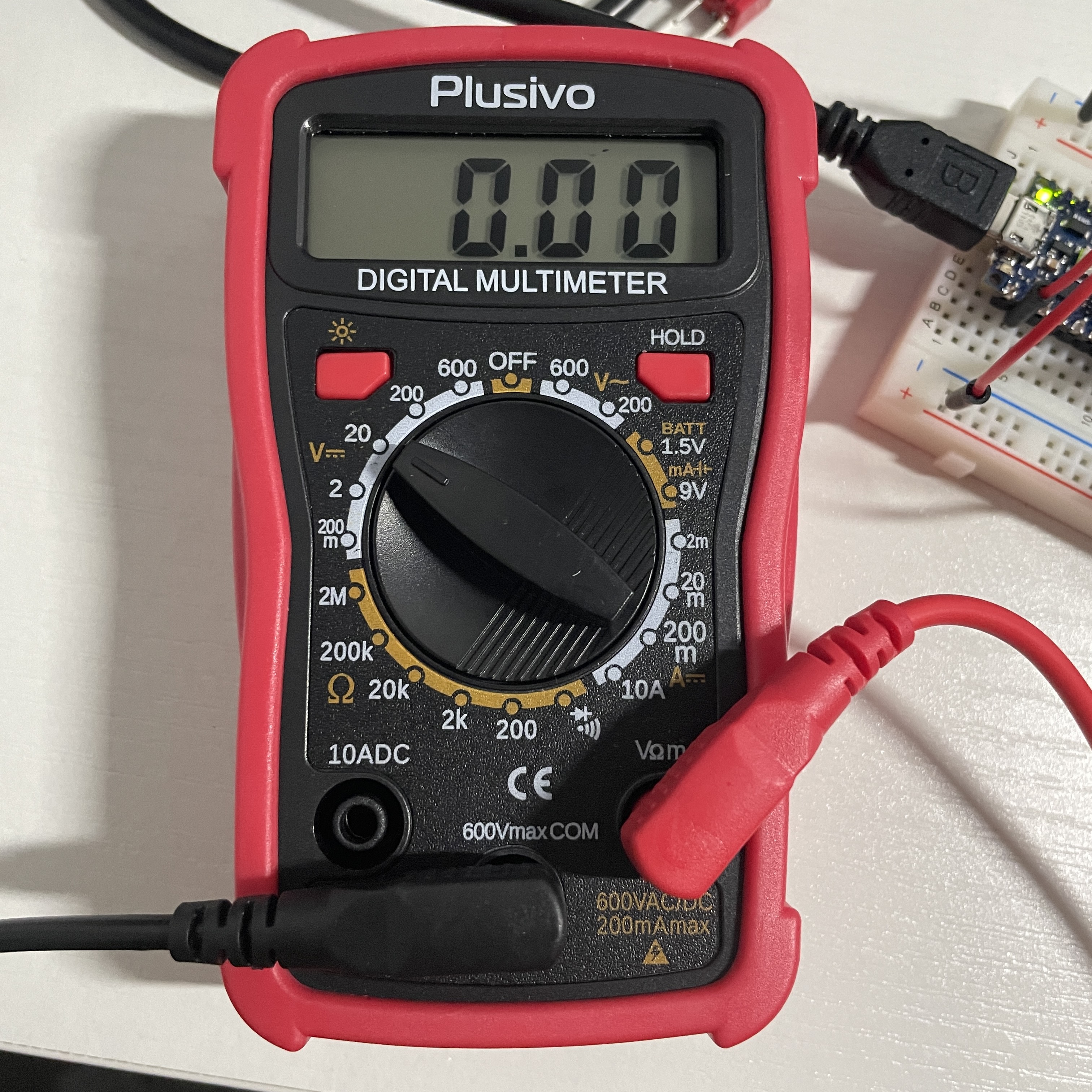
Multimeter
According to the lab resource, I connect the NANO board with computer through USB cable to charge the NANO board. Since the pin infos are under the NANO board after I attach it to the breadboard, I found the pin info picture from internet to remind me.


Without the AWG solid core hookup wires, I connect pin 15 to the power+ line on breadboard because LED needs a digital input, and connect the GND of NANO board to the ground- line of breadboard. Therefore, the red line and the blue line on breadboard are like the entry and exist for the circuit to be formed.


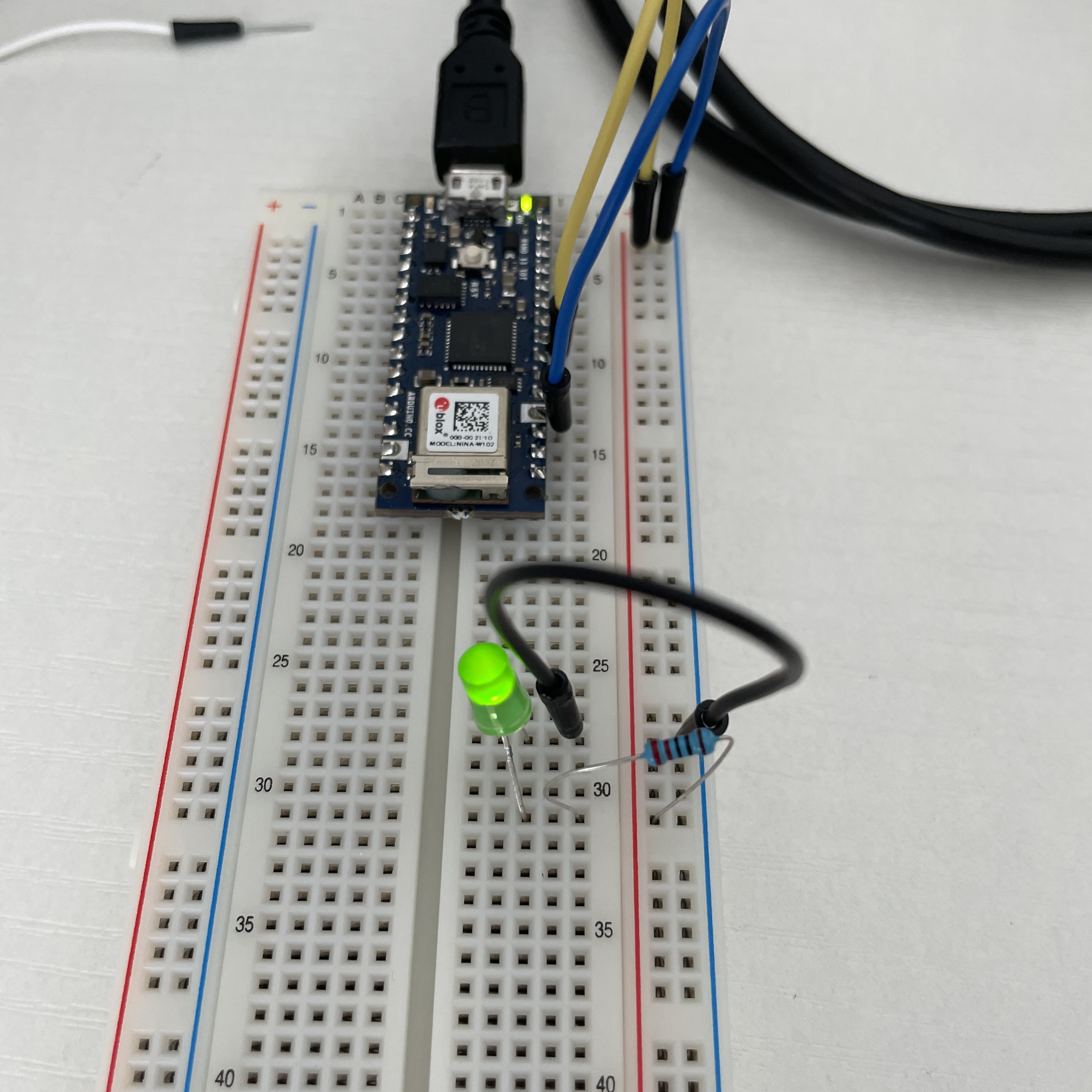
I connect the circuit like the photo appears, open the example file of “Blink” and upload to the board to test the circuit. The LED blinks, the circuit works. But I wonder if the two legs of LED are different, so I changed the positions of two legs.
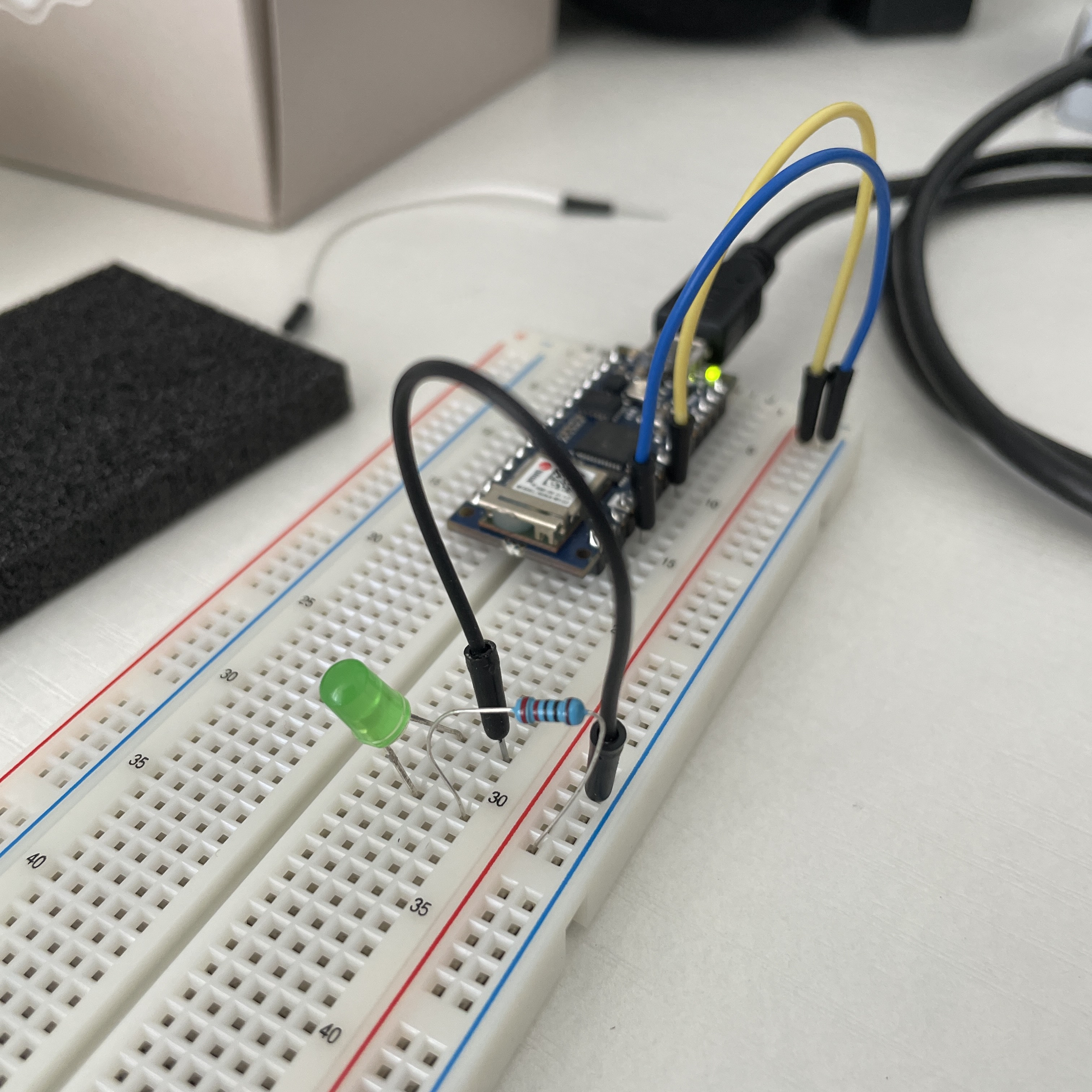

The LED doesn’t work this time, so the longer leg is the positive side of LED.
Electronics and using a Multimeter
Power supplied by computer:


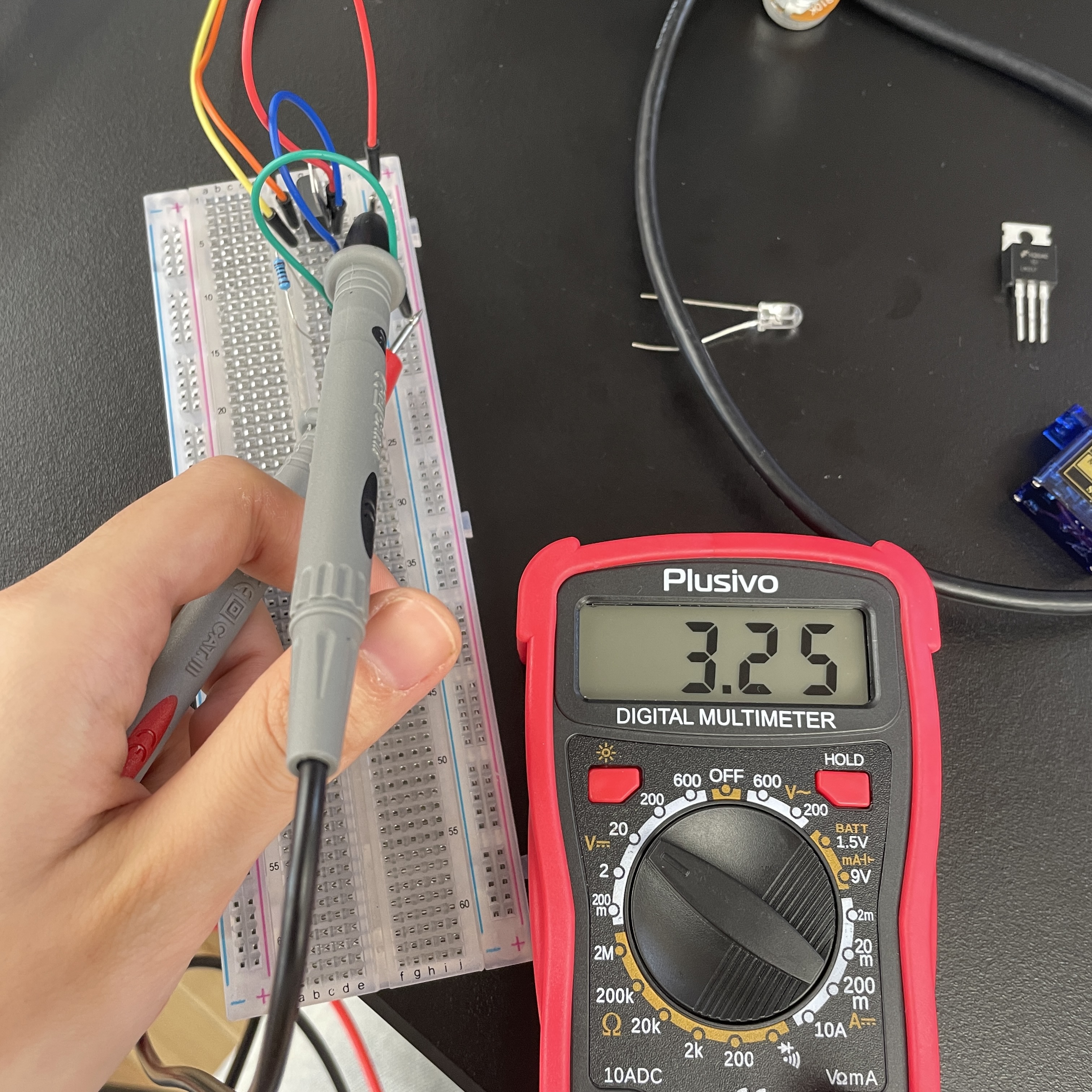
The first time I use multimeter, the resistance is 220Ω. When I touch the + and - line on breadboard, it says 2.94V. Then I touch the left and the right side of LED, it says 2.09V. So the LED has 2/3 of the voltage.


I touch the both sides of resistance and it says 1242Ω. And the LED’s resistance is 1970Ω. The result is compatible with the voltage I have tested.
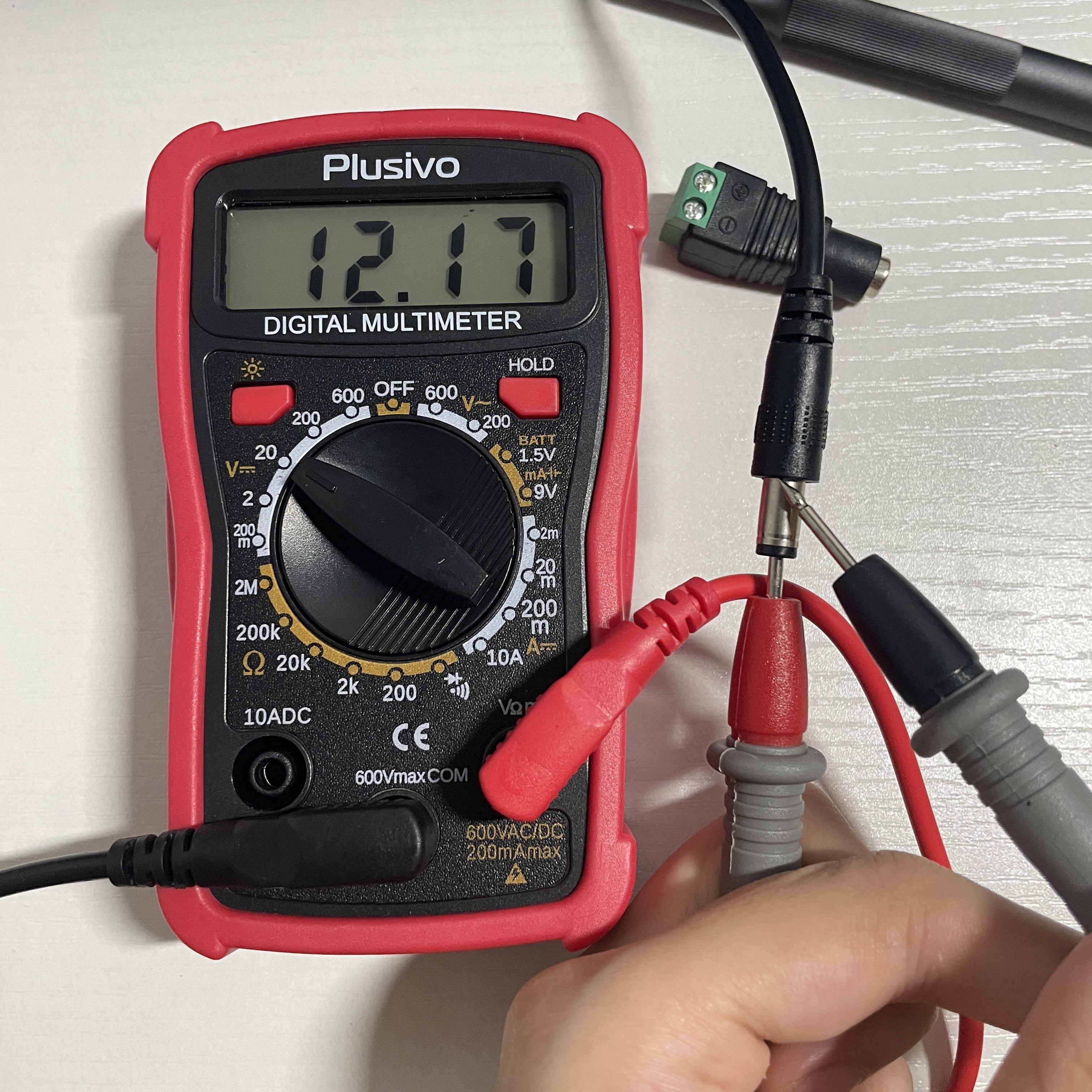
Power supplied by DC power supply:
I use the DC power supply of 12V and test it with multimeter, it’s around 12V correctly. And I plug a voltage regulator LM317 on the breadboard and the multimeter says the voltage is around 3.3V correctly.
 .
. 
Switches
The things I have:
NANO 33 IoT
USB cable
wire
1KΩ resistanceLED
breadboard
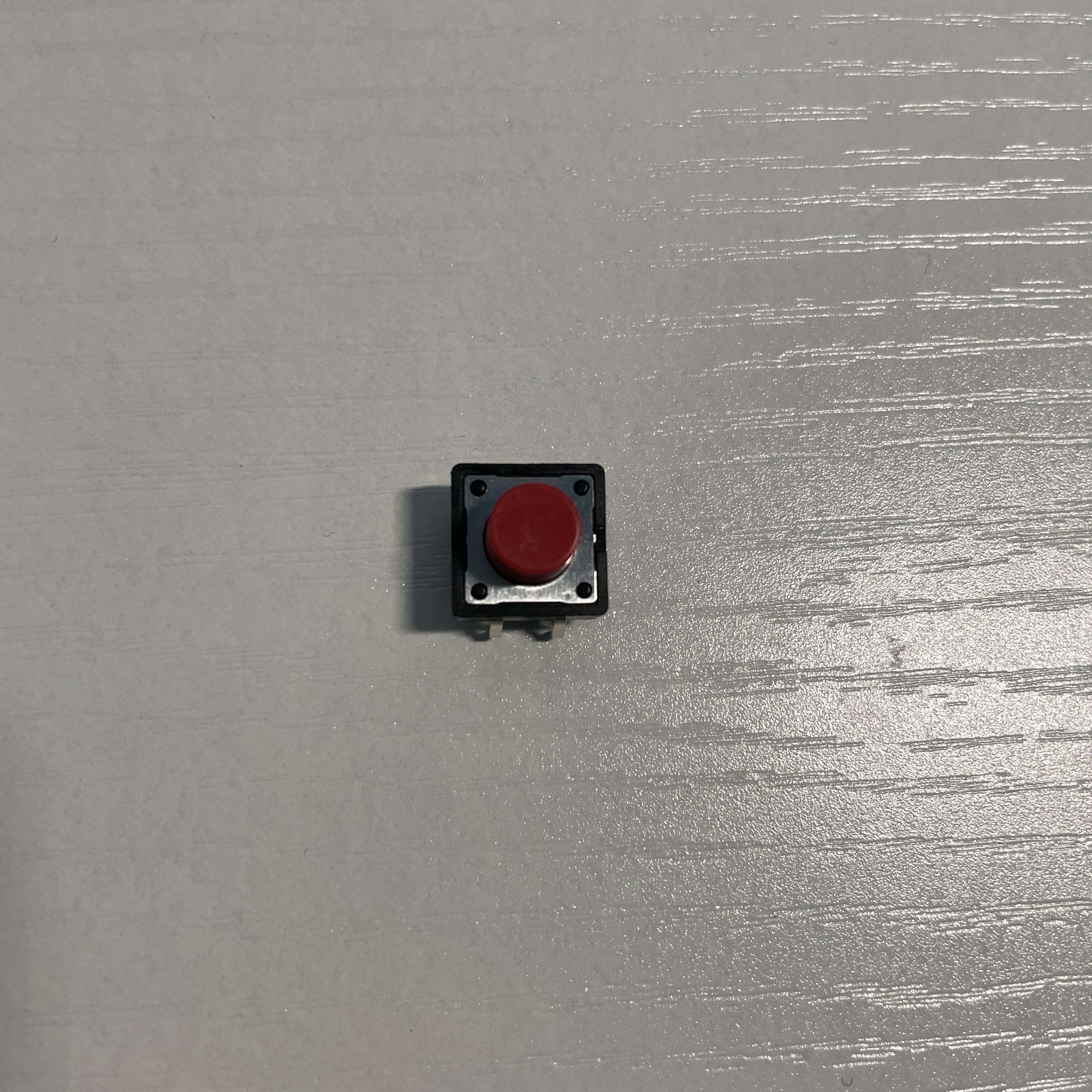
Button
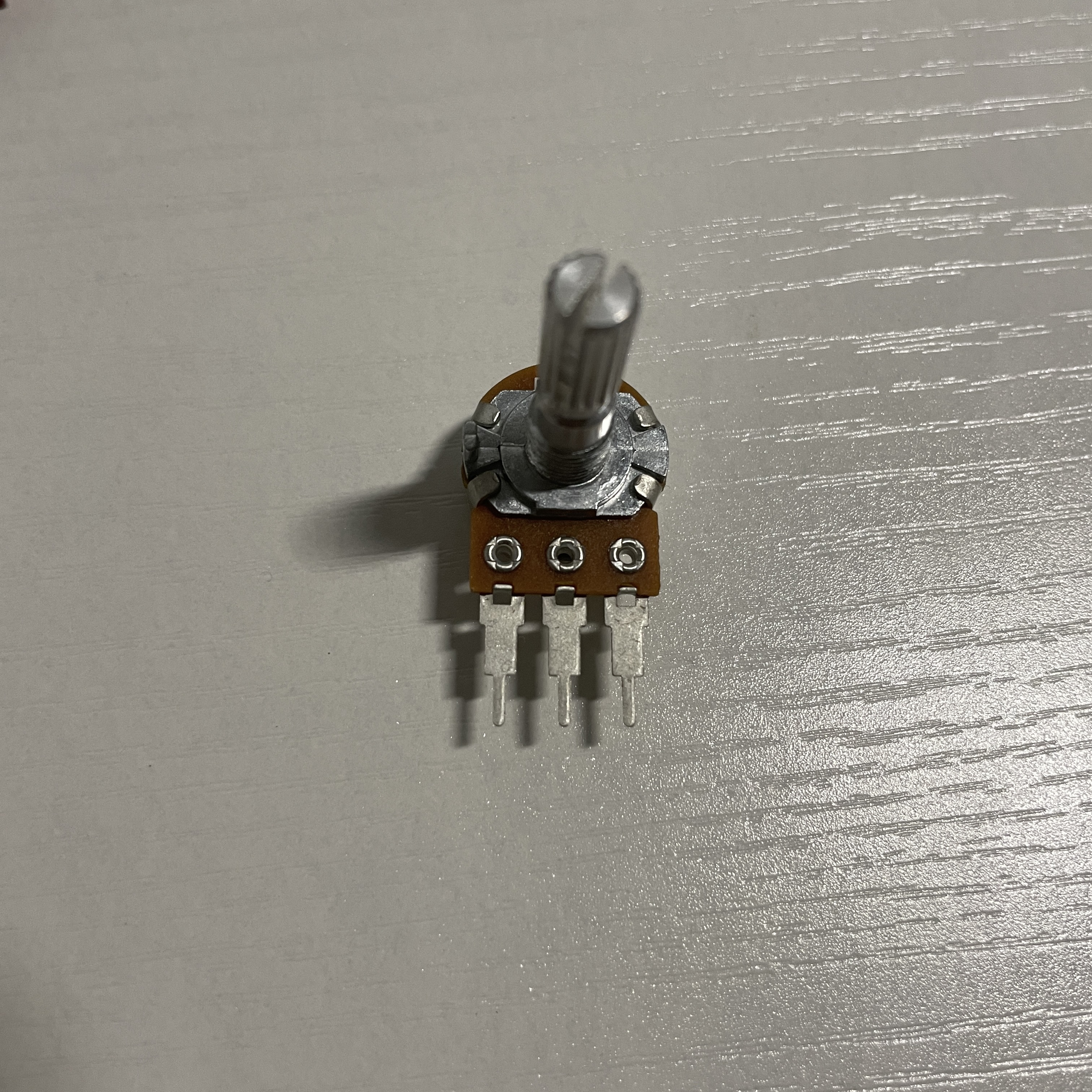
Potentiometer
Button
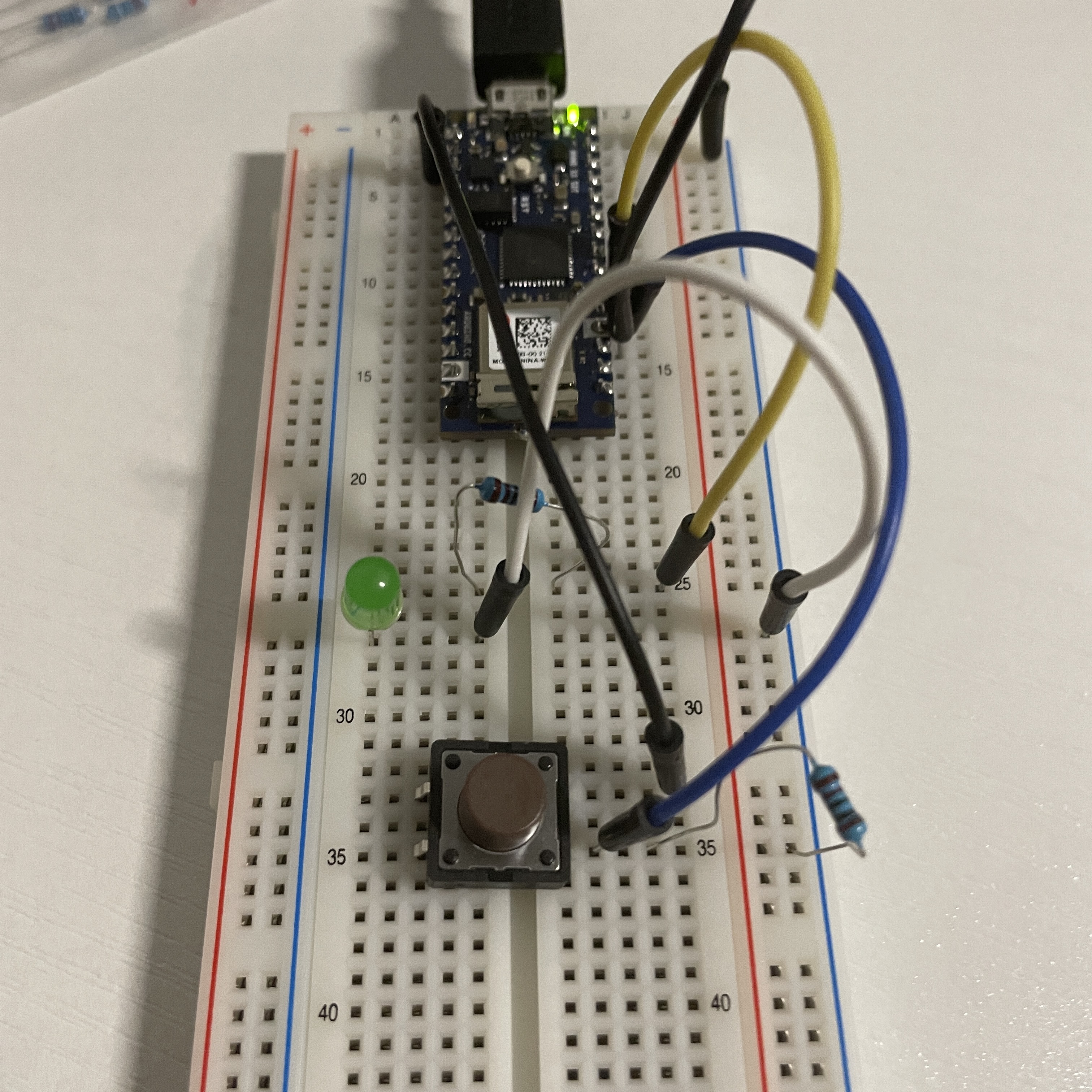
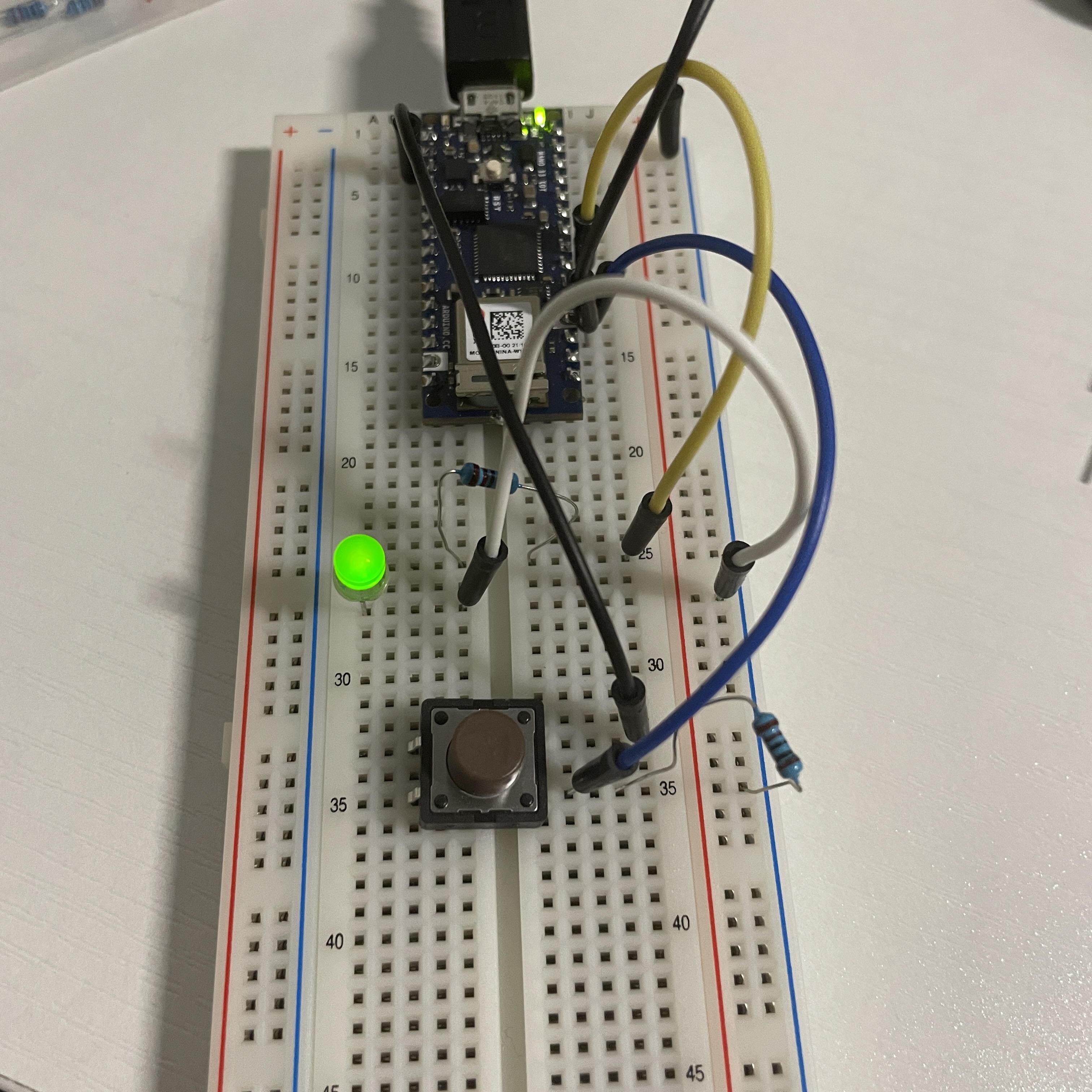
Based on the former circuit, I insert the button in it so it can act as a switch in series circuit. When I press on the button, LED will be turned on, vise versa.
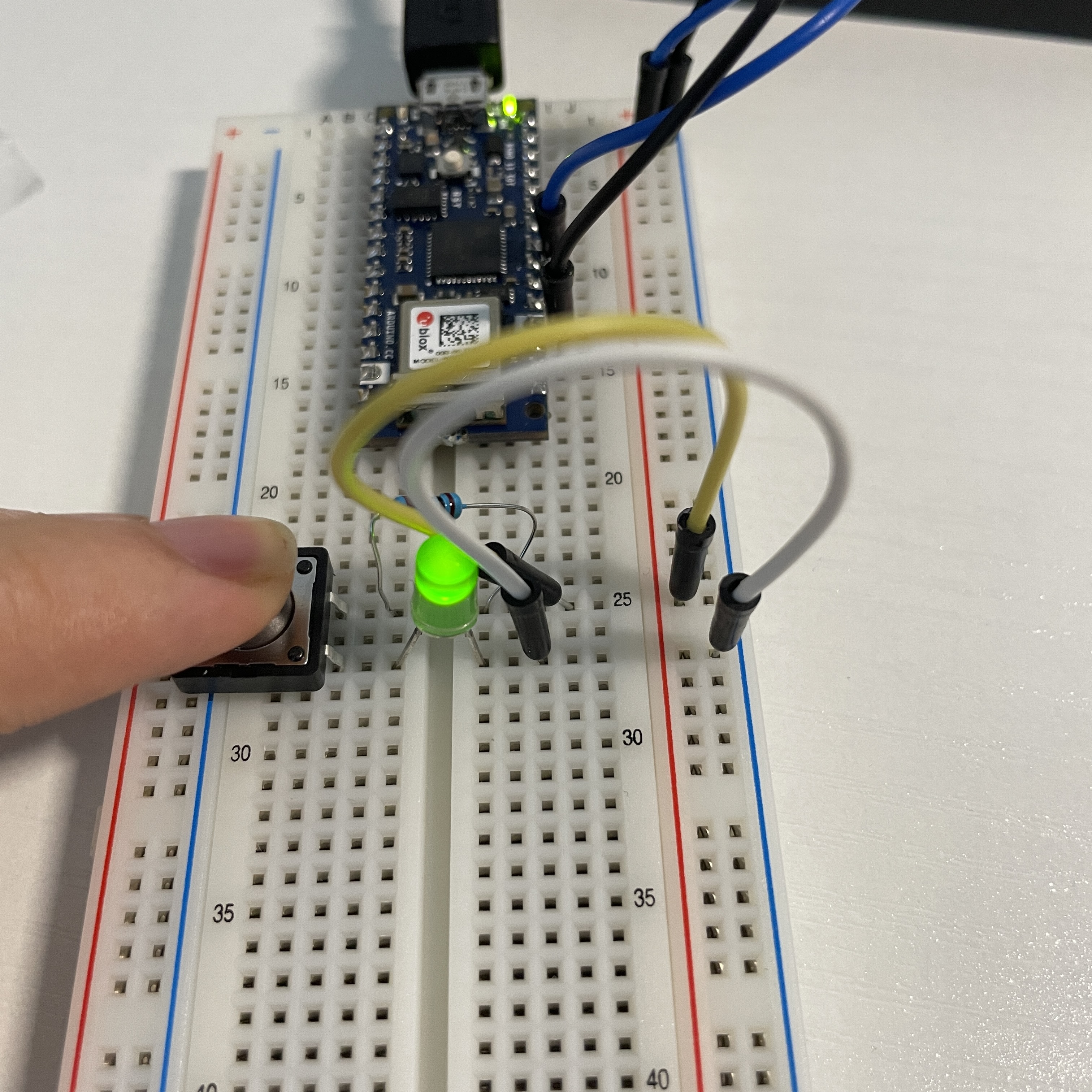
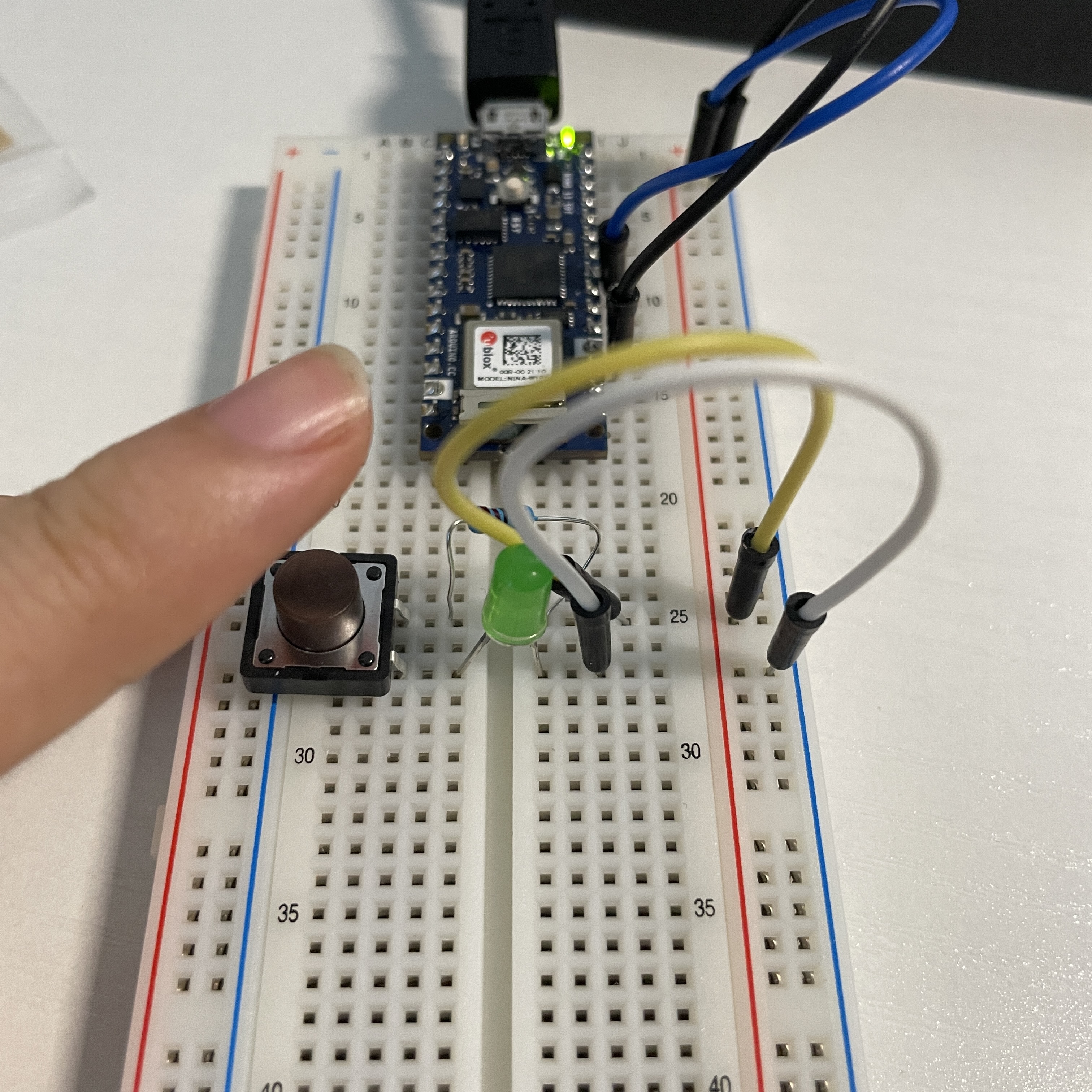
I try to make the button situation similar to the real bavior. I want the light to be turned on at the first press and to be turned off at the second press.

But it occurs that the button sometimes doesn’t work, the LED swiftly turns on and off at the same press. So I search for the methods to eliminate the vibration error of button. The first way is to use delay() but it will delay the whole program. The seconde way is use lastButtonState and currentButtonState. The third way is to install the Bounce library of Arduino.
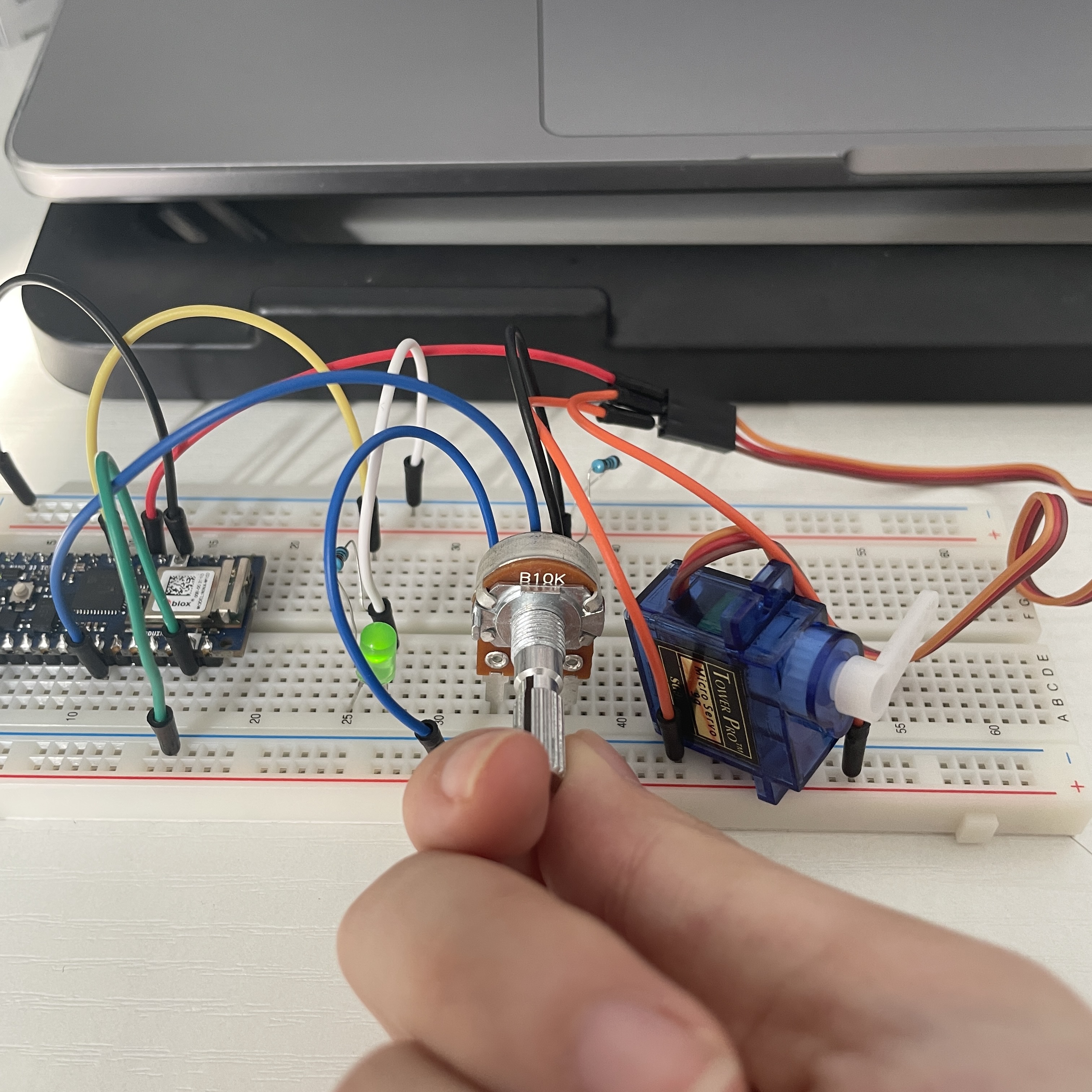
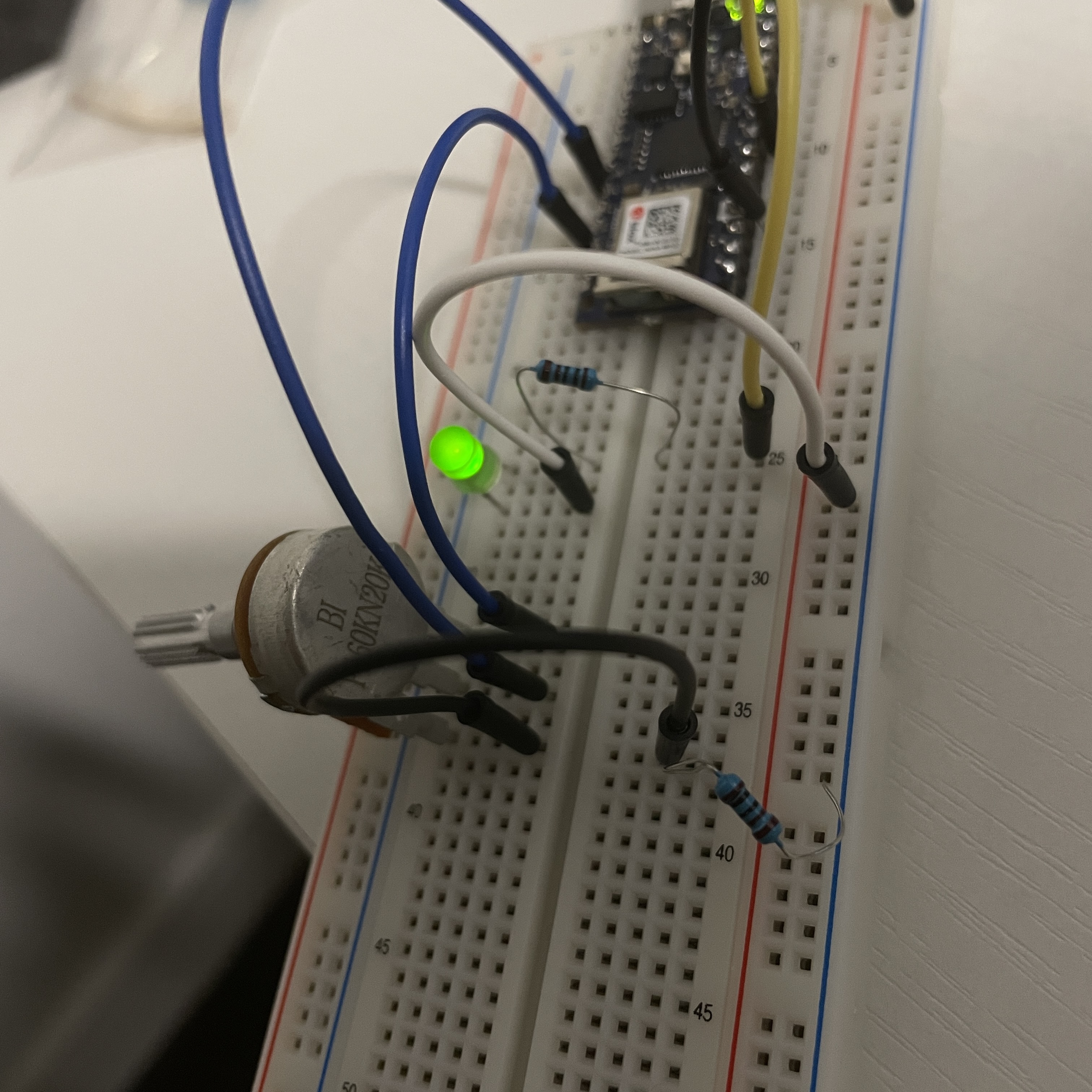
Potentiometer
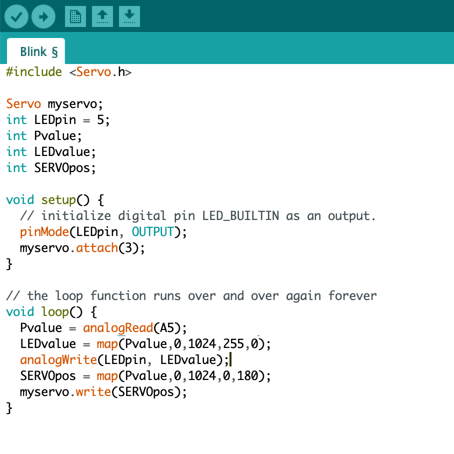
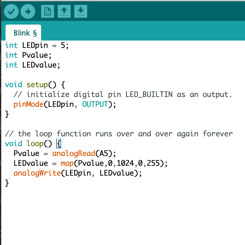
The button is digital inputs which has only 0 or 1, but potentiometer is analog input which has a span of value. So it has to be analogRead( ) function to be called to read the analog value of potentiometer. Here I discover that I have to use map( ) to transform the spectrum of potentiometer value into the spectrum of LED value.

Thinking about what else potentiometer can control, I try to put the servo into the circuit. So when I twist the potentiometer from left to the right, the LED turns brighter and the servo turns to the right.